Technician holding a portable gas detector probe near a valve in a process facility

Guide

EPA Method 21: VOC Leak Detection Procedure and Instrument Requirements

Last updated:

EPA Method 21 is the U.S. Environmental Protection Agency’s procedure for finding volatile organic compound (VOC) leaks from process equipment with a portable instrument. Its formal title is “Determination of Volatile Organic Compound Leaks,” and it is published in 40 CFR Part 60, Appendix A-7. Method 21 locates and classifies leaks. It does not measure how much a component emits.

Method 21 is also only half of any compliance requirement. The method defines how the instrument must perform and how a technician surveys each component. The regulation that calls for Method 21 decides which equipment is monitored, how often, what reading counts as a leak, and what happens after a leak is found. Keeping those two layers separate answers most practical questions about EPA Method 21 leak detection, including how often to calibrate and which leak definition applies.

This guide explains what Method 21 requires, how a Method 21 survey is performed, what the instrument must meet, which detector types can qualify, and when optical gas imaging (OGI) can be used instead.

What Is EPA Method 21?

Method 21 is a reference test method for detecting VOC leaks at individual equipment components. A technician places the inlet of a portable analyzer’s sample probe at the surface of a component interface where leakage could occur, finds the highest reading, and compares it with the leak definition in the applicable regulation.

The method applies to process equipment such as valves, flanges and other connections, pumps and compressors, pressure relief devices, process drains, open-ended valves, seal system degassing vents, accumulator vessel vents, agitator seals, and access door seals. Section 1.2 of the method presents that list as examples, not a complete set.

Three points from the method’s summary in Section 2.1 shape everything else about it:

  • The detector type is not specified. Any portable instrument can be used if it meets the specifications and performance criteria in Section 6.
  • The leak definition comes from the regulation. Each applicable regulation sets a leak definition concentration based on a reference compound.
  • It locates and classifies leaks only. The method states that it is not to be used as a direct measure of the mass emission rate from individual sources.

The last point matters when planning a monitoring program. A Method 21 reading shows whether a component exceeds a rule’s leak definition when it is surveyed. It does not tell you how many grams or pounds per hour that component releases.

Where to find the official text. The current text of Method 21 is in 40 CFR Part 60, Appendix A-7, which you can read on eCFR. eCFR is updated continuously, while the annually published CFR on govinfo.gov is the official legal edition. EPA’s Emission Measurement Centre also posts the method on its Method 21 page, including a PDF dated August 3, 2017. That PDF notes that it is not the official version and directs readers to eCFR for recent edits.

Key Method 21 terms

A few defined terms recur in every regulation that references Method 21. The definitions below are paraphrased from Section 3 of the method, with a note on why each one matters in practice.

TermWhat it meansWhy it matters
Leak definition concentrationThe local VOC concentration at the surface of a leak source that indicates a leak is present, expressed as an instrument reading based on a reference compound.The number comes from the applicable regulation, not from Method 21.
Reference compoundThe VOC used as the instrument’s calibration basis for the leak definition. The method’s example: if the leak definition is 10,000 ppm as methane, a reading of 10,000 on an instrument calibrated with methane is a leak.A leak definition is incomplete without its reference compound.
Response factorThe ratio of a compound’s known concentration to the meter reading when the instrument is calibrated with the reference compound specified in the regulation.Shows how well a detector responds to the compounds actually present in the process stream.
Response timeThe time from a step change in VOC concentration at the sampling system inlet until the readout reaches 90 percent of the final value.Sets how long the probe stays at the maximum-reading location during a survey.
Calibration precisionThe agreement between repeated readings of the same known concentration, expressed as a percentage of that concentration.One of the performance checks required before an analyzer is placed into service.
No detectable emissionA local VOC concentration at the surface of a source, adjusted for the local ambient concentration, that is less than 2.5 percent of the leak definition.Applies only where a regulation sets a no-detectable-emission standard. Some subparts set their own comparison value; Subpart VVa, for example, compares the reading above background with 500 ppm.

These terms explain why two facilities can both “use Method 21” and still have different leak thresholds, calibration gases, and survey steps: the regulation fills in the values the method leaves open.

EPA Method 21 vs. other methods numbered 21

Search results for “method 21” can also include a Bay Area Air Quality Management District (BAAQMD) laboratory procedure with the same number. That procedure covers coatings analysis, not equipment leaks, and is unrelated to EPA Method 21. EPA Method 22 is also a different method; the FAQ explains how it differs.

How Method 21 Fits an LDAR Program

Method 21 is the measurement procedure inside many leak detection and repair (LDAR) requirements, not the requirement itself. A rule that requires Method 21 monitoring decides which equipment is covered, how often it is monitored, the leak definition, repair timing, and recordkeeping. Method 21 governs how the instrument performs and how each component is surveyed. For how those pieces come together in a full program, see MFE’s guide to LDAR programs.

The method is referenced across EPA’s air rules. EPA’s 2008 OGI alternative work practice, for example, is written to be available to any subpart in 40 CFR parts 60, 61, 63, and 65 that requires monitoring with a Method 21 monitor (40 CFR 60.18(a)(2) and (h)). Method 21 LDAR surveys are also one part of broader fugitive emissions monitoring at regulated facilities.

What Method 21 compliance depends on

Method 21 compliance always has two parts: an instrument and survey technique that meet the method, and a program that meets the applicable subpart. The table below shows which document sets each requirement.

QuestionSet by Method 21?Set by the applicable subpart?
Which facilities and components must be monitoredNo. The method lists the kinds of sources it can be applied to.Yes
How often components are monitoredNoYes
Leak definition concentration and reference compoundNo. Section 2.1 says each applicable regulation specifies them.Yes
Instrument performance (detector response, meter readability, pump flow, probe size, intrinsic safety, response factor, calibration precision, response time)Yes, in Sections 6 and 8.1. See instrument requirements.Sometimes adjusts them; for example, the response factor limit applies “unless otherwise specified in the applicable regulation.”
Calibration before a surveyYes. The instrument is calibrated before use according to Section 10.Often adds frequency, calibration gases, and end-of-day drift checks (examples below).
How each component is surveyedYes, in Section 8.3.Decides whether a no-detectable-emission (Type II) survey applies.
Repair deadlines, recordkeeping, and reportingNo. The method says to record and report results as the regulation specifies.Yes

For buyers, the practical result is a two-part check. An instrument has to meet Method 21’s performance specifications, and the program using it has to meet the subpart’s calibration gases, monitoring frequency, and records. A product described as suitable for Method 21 addresses only the first part.

Two examples of what a subpart adds

The two rules below show how much a referencing subpart can add to the method. They are examples, not a complete list, and the subpart that applies to a specific unit controls.

NSPS Subpart VVa (synthetic organic chemicals manufacturing). Subpart VVa covers affected facilities in the synthetic organic chemicals manufacturing industry that commenced construction, reconstruction, or modification after November 7, 2006, and on or before April 25, 2023. Its test-methods section, 40 CFR 60.485a, requires Method 21 to determine the presence of leaking sources, then adds requirements that Method 21 itself does not contain:

  • Calibrate the instrument before use each day of its use, following the Method 21 procedures.
  • Use zero air (less than 10 ppm of hydrocarbon in air) and a methane or n-hexane calibration mixture no more than 2,000 ppm above the leak definition concentration of the equipment monitored.
  • Perform a calibration drift assessment at least at the end of each monitoring day. A negative drift of more than 10 percent requires re-monitoring of equipment whose readings since the last calibration fall in the band the rule specifies.
  • For no-detectable-emission standards, compare the maximum reading minus the background level with 500 ppm.

Because of its date range, Subpart VVa does not cover every unit in that industry. EPA added a separate Subpart VVb in May 2024, so confirm which subpart applies before relying on any example here.

NSPS Subpart OOOOb (crude oil and natural gas). OOOOb’s fugitive emissions program allows OGI or Method 21 monitoring at certain site types, and the rule sets which sites and survey frequencies apply (MFE’s OOOOa compliance guide covers the earlier OOOOa rule). When Method 21 is used, a fugitive emission is an instrument reading of 500 ppmv or greater (40 CFR 60.5397b). For instrument capability, the rule defines that threshold as 500 ppmv methane on an FID-based instrument. An operator using another analyzer type must develop a site-specific definition equivalent to 500 ppmv methane on an FID-based instrument, and the rule gives a 10.6 eV PID with a specified isobutylene concentration as an example. OOOOb’s Method 21 provisions also include their own calibration and drift-assessment requirements.

That PID example does not mean a PID detects methane. It describes an equivalent response to the compound of interest, which is why detector choice deserves its own check; see detector types.

How Method 21 Monitoring Is Performed

Method 21 monitoring is a component-by-component survey with a calibrated portable analyzer. The technician traces the probe around each potential leak interface, finds the highest reading, holds the probe there, and compares that reading with the leak definition in the applicable regulation. Method 21 describes three survey techniques: a concentration-based survey (Type I), a no-detectable-emission survey (Type II), and an alternative soap-bubble screening procedure.

Before any survey, the instrument must have passed its performance checks and been calibrated. Those requirements are covered under Method 21 instrument requirements.

Type I survey: leak definition based on concentration

Most Method 21 monitoring is a Type I survey, described in Section 8.3.1. The steps are:

  1. Place the probe inlet at the surface of the component interface where leakage could occur.
  2. Move the probe along the interface periphery while watching the instrument readout.
  3. If the reading rises, slowly sample the interface where leakage is indicated until you find the maximum reading.
  4. Leave the probe inlet at that maximum-reading location for approximately two times the instrument’s response time.
  5. If the maximum reading is greater than the leak definition in the applicable regulation, record and report the result as that regulation specifies.

The dwell step is the reason response time matters in the field. An instrument with a slower response needs a longer hold at each maximum, which adds time to every component that shows an elevated reading.
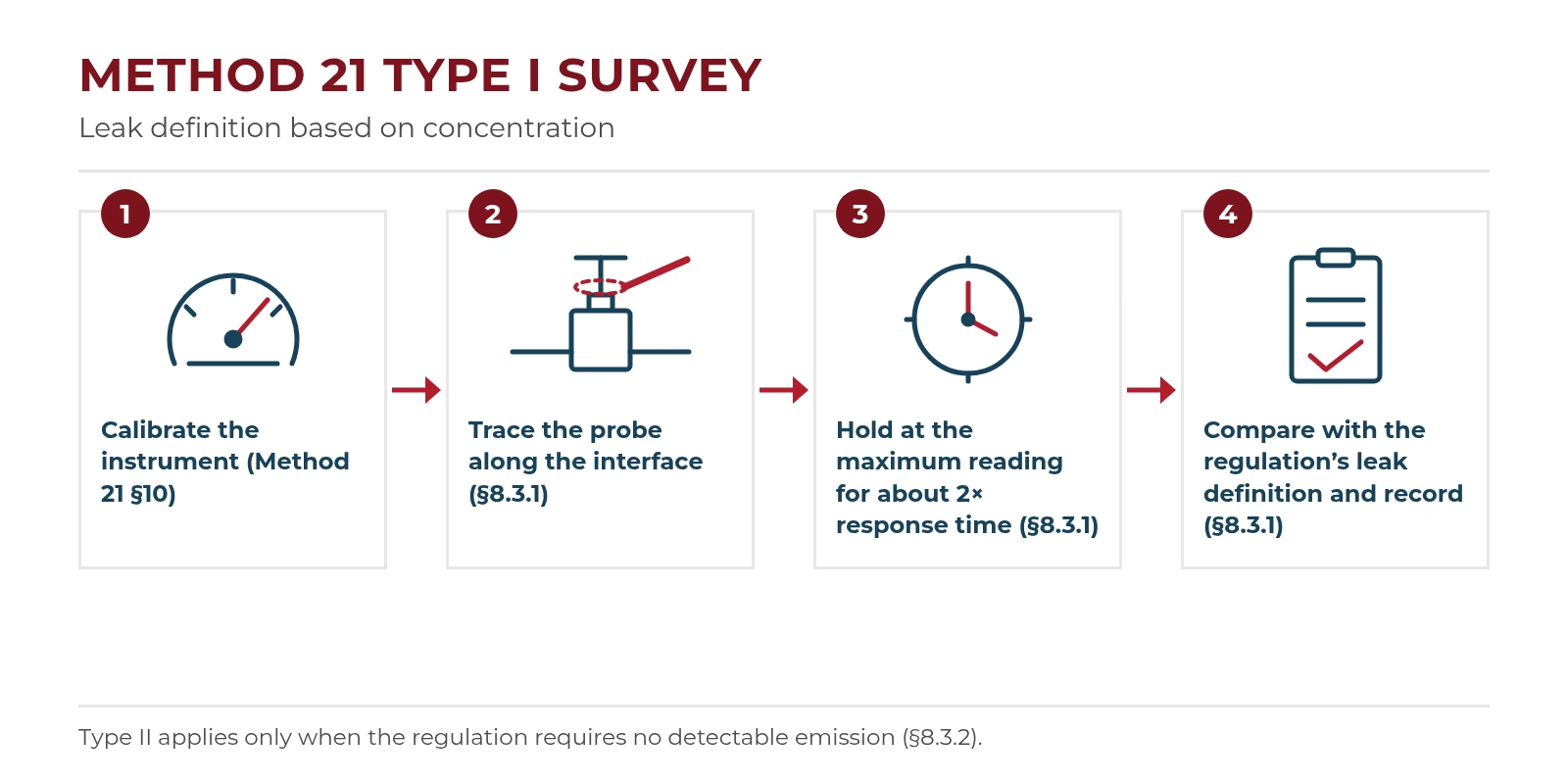
Four-step diagram of a Method 21 Type I survey: calibrate, trace the probe along the interface, hold at the maximum reading, compare with the leak definition

Where to place the probe on common components

Method 21 gives component-specific placement instructions because leaks concentrate at different interfaces on different equipment. The table below summarizes Sections 8.3.1.1 through 8.3.1.8.

ComponentWhere to place the probe
ValvesSample the stem circumference where the stem exits the packing gland, which the method identifies as the most common source of valve leaks. Also sample the periphery of the packing gland take-up flange seat, and every interface on multipart valve housings where a leak could occur.
Flanges and other connectionsFor welded flanges, place the probe at the outer edge of the flange-gasket interface and sample the circumference. Use a similar traverse on threaded and other nonpermanent joints.
Pumps and compressorsTraverse the outer surface of the shaft and seal interface. For a rotating shaft, keep the probe inlet within 1 cm of the shaft-seal interface. If the housing prevents a full traverse, sample all accessible portions, plus any other housing joints where leakage could occur.
Pressure relief devicesMost configurations prevent sampling at the sealing seat. For devices with an enclosed extension, or horn, place the probe inlet at approximately the centre of the exhaust area to the atmosphere.
Process drainsFor open drains, place the probe inlet at approximately the centre of the area open to the atmosphere. For covered drains, traverse the cover interface.
Open-ended lines or valvesPlace the probe inlet at approximately the centre of the opening to the atmosphere.
Seal system degassing vents and accumulator ventsPlace the probe inlet at approximately the centre of the opening to the atmosphere.
Access door sealsPlace the probe inlet at the surface of the door seal interface and traverse the periphery.

These instructions assume the technician can physically reach each interface. Pump housings, elevated valves, and insulated or congested piping can limit that access, which is one reason survey planning matters as much as the instrument.
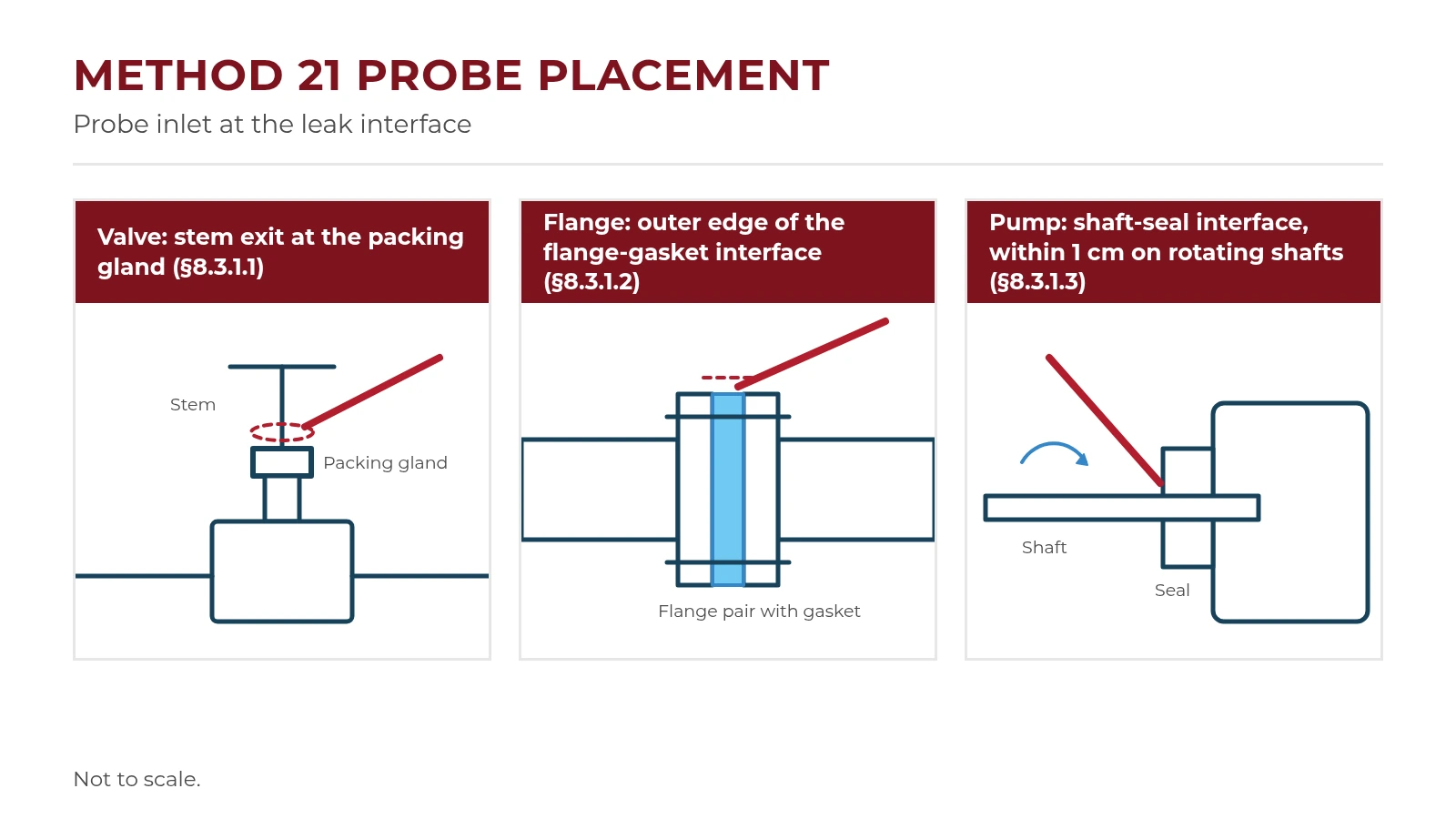
Line drawings showing probe placement at a valve packing gland, the outer edge of a flange gasket, and a pump shaft seal

Type II survey: “no detectable emission”

A Type II survey applies only when the applicable regulation sets a no-detectable-emission standard for a source. The method’s own examples are pump and compressor seals, seal system degassing vents, accumulator vessel vents, and pressure relief devices. It is not a step in every Method 21 survey. Section 8.3.2 adds a background measurement to the Type I technique:

  1. Determine the local ambient VOC concentration by moving the probe randomly upwind and downwind at one to two meters from the source.
  2. If a nearby emission or leak interferes, the ambient reading may be taken closer to the source, but never closer than 25 centimetres.
  3. Move the probe inlet to the surface of the source and measure as in a Type I survey.
  4. Use the difference between the two readings to determine whether there are no detectable emissions, and record and report as the regulation specifies.

Where a regulation requires a specific device or requires vents to be ducted or piped to a control device, the method calls for visual confirmation of those conditions. When the regulation also requires no detectable emissions, both visual observations and sampling surveys are required. For seal system degassing vents, accumulator vessel vents, and pressure relief devices, the method presumes no detectable emissions when the required ducting or piping exists and there are no points upstream of the control device where emissions could reach the atmosphere. If such points exist, the Type II sampling survey applies.

Alternative screening with a soap solution

Section 8.3.3 allows a soap-bubble screening procedure as an alternative to the instrument for some sources. A soap solution, either a commercial leak detection solution or a detergent-and-water mix, is sprayed over potential leak sources. If no bubbles form, the source is presumed to have no detectable emissions or leaks, as applicable. If bubbles form, the instrument technique of Type I or Type II must be used to determine whether a leak exists.

The procedure cannot be used on sources that have continuously moving parts, surface temperatures above the boiling point or below the freezing point of the soap solution, open areas to the atmosphere that the solution cannot bridge, or evidence of liquid leakage. Those sources must be surveyed with the instrument.

Method 21 itself stops at recording and reporting results “as specified in the regulation.” Leak tagging, repair deadlines, re-monitoring after repair, and records belong to the applicable subpart and the facility’s LDAR program.

Method 21 Instrument Requirements

Method 21 does not name an instrument or detector type. Any portable VOC monitoring instrument can be used if it meets the hardware specifications in Section 6, uses the zero and calibration gases in Section 7, and passes the performance checks in Section 8.1. The requirements below are taken from the method text; your subpart may adjust some of them.

Hardware specifications (Section 6)

RequirementMethod 21 specificationSection
Detector responseThe detector must respond to the compounds being processed. Catalytic oxidation, flame ionization, infrared absorption, and photoionization are listed as types that may meet this requirement, without limiting the options to those four.6.1
Measuring rangeCapable of measuring the leak definition concentration specified in the regulation.6.2
Meter readabilityThe meter scale must be readable to ±2.5 percent of the specified leak definition concentration.6.3
Sample pumpAn electrically driven pump that delivers sample to the detector at a constant flow rate. Nominal flow, measured at the probe tip with any glass wool plug or filter used to prevent plugging in place, is 0.10 to 3.0 L/min (0.004 to 0.1 ft³/min).6.4
ProbeProbe, probe extension, or sampling line no more than 6.4 mm (1/4 in.) in outside diameter, with a single end opening for sample admission.6.5
Intrinsic safetyIntrinsically safe for operation in explosive atmospheres; at a minimum, for Class 1, Division 1 and/or Class 2, Division 1 conditions, as appropriate, as defined by the National Electrical Code or other applicable code. The instrument must not be operated with any safety device, such as an exhaust flame arrestor, removed.6.6

Gases and performance checks (Sections 7 and 8.1)

Before an analyzer is placed into service, Method 21 requires three performance evaluations: response factor, calibration precision, and response time. Each has its own repeat interval, and the gases used for them have their own accuracy requirements.

RequirementMethod 21 specificationWhenSection
Zero gasAir with less than 10 ppmv VOC.Each calibration and performance check7.1.1
Calibration gasA known standard in air for each organic species to be measured, at approximately the leak definition concentration. Cylinder gases must be certified by the manufacturer to within 2 percent accuracy, with a specified shelf life. User-prepared gases must be accurate to within 2 percent and replaced each day of use unless degradation is shown not to occur in storage. A compound other than the reference compound may be used with a conversion factor.Each calibration and performance check7.1.2–7.4
Response factorLess than 10 for each individual VOC to be measured, unless the applicable regulation specifies otherwise. Determined by testing or taken from published response factors for the instrument or detector type.Before placing into service; does not have to be repeated8.1.1
Calibration precisionEqual to or less than 10 percent of the calibration gas value, based on three alternating zero-gas and calibration-gas measurements.Before placing into service, then at 3-month intervals or the next use, whichever is later8.1.2
Response timeEqual to or less than 30 seconds, measured with the pump, any dilution probe, the sample probe, and the probe filter that will be used during testing in place.Before placing into service; repeated if the sample pumping system or flow configuration is modified in a way that would change response time8.1.3

Two details are easy to miss. The response time has to be demonstrated with the probe and filter that will actually be used, so changing the sampling configuration can require a new test. And the response factor limit is about the compounds in the process stream, not only the calibration gas, which is why detector type matters; see detector types.

Calibration: what Method 21 requires vs. what your subpart adds

Method 21 requires the instrument to be calibrated before use. Section 10.1 describes the procedure: after the warm-up period and zero internal calibration, introduce the calibration gas into the sample probe and adjust the meter readout to the calibration gas value. If the readout cannot be adjusted to the proper value, the method treats that as an analyzer malfunction that must be corrected before use.

The method does not itself say to calibrate daily, or to check the instrument again at the end of the day. Those requirements come from the subparts that reference Method 21. Summaries that describe Method 21 as requiring “daily” calibration are combining the method with a typical subpart.

CheckMethod 21Example subpart addition
Calibration before monitoringCalibrate before use according to Section 10 (Section 8.2).Subpart VVa: before use each day of its use, with specified zero air and methane or n-hexane calibration gas (40 CFR 60.485a(b)(1)).
Calibration precision testBefore service, then at 3-month intervals or the next use, whichever is later (Section 8.1.2).Check the applicable subpart for any change to this interval.
End-of-day drift checkNot required by the method.Subpart VVa: at least at the end of each monitoring day, with re-monitoring when negative drift exceeds 10 percent (40 CFR 60.485a(b)(2)).

For a monitoring program, the practical rule is to calibrate and check drift as often as your subpart requires, using the gases it specifies, and to keep the Method 21 precision test on its own schedule. The subpart examples above show how VVa and OOOOb add to the method.

When evaluating an instrument for Method 21 work, these requirements translate into specific questions for the manufacturer’s documentation: the detector’s response factors for the compounds you monitor, the intrinsic safety rating for your area classification, the response time with the probe and filter you will use, and the meter readability at your leak definition.

Detector Types: FID, PID, and Others

Method 21 does not require a specific detector. Section 6.1 requires only that the detector respond to the compounds being processed, and it lists catalytic oxidation, flame ionization, infrared absorption, and photoionization as types that may meet that requirement, without limiting the choice to those four. Whatever the detector, the instrument still has to meet the rest of Section 6 and pass the response factor, calibration precision, and response time checks.

Detector choice matters because each type responds differently to different compounds. The same gas stream can produce different readings on two compliant instruments, which is why response factors and the regulation’s reference compound sit at the centre of instrument selection.

Detector typeHow it detectsResponse to methanePractical notes
Flame ionization (FID)Burns the sample in a hydrogen flame and measures the current from the resulting ions.Responds. An FID is often calibrated with methane.Broad response to hydrocarbons. Needs hydrogen fuel, and oxygen to sustain the flame, which portable FIDs usually draw from the sample air.
Photoionization (PID)Ionizes the sample with ultraviolet light from a lamp; the lamp energy changes which compounds are ionized.None. Methane’s ionization energy (12.6 eV) is too high for any PID lamp.Commonly calibrated with isobutylene or benzene. Sensitivity varies strongly by compound and lamp.
Catalytic oxidationMeasures the heat released when combustible gases oxidize on a catalyst-coated sensing element.Depends on the instrument and its calibration.Method 21 cites published response factors for this detector type (Section 8.1.1.3).
Infrared absorptionMeasures absorption at wavelengths characteristic of the target compound.Depends on the wavelength the instrument targets.Can be selective for a compound, but other compounds that absorb at similar wavelengths can interfere.

Sources: Method 21 Section 6.1; EPA, Survey of Portable Analyzers for the Measurement of Gaseous Fugitive Emissions (1992); RAE Systems by Honeywell, Application Note AP-226.

Why PIDs and methane need extra care

A standard PID cannot detect methane. EPA’s 1992 survey of portable analyzers states that PIDs do not respond to methane, and RAE Systems’ application note explains why: methane’s 12.6 eV ionization energy is beyond the reach of any PID lamp. Any reading a PID gives in a methane-bearing stream comes from other compounds the lamp can ionize.

That matters because methane appears throughout Method 21 work. The method’s own reference-compound example uses methane. Subpart VVa allows methane or n-hexane as the calibration gas. In oil and gas, OOOOb defines its Method 21 threshold as 500 ppmv methane on an FID-based instrument, and it allows a PID only through a site-specific fugitive emission definition equivalent to that threshold for the compound of interest (see subpart examples).

The practical rule: if the leak definition is expressed as methane, or the stream is mostly methane, start with an instrument that responds to methane, such as an FID, and confirm the subpart’s requirements. A PID can still be appropriate for streams of compounds it responds to well, provided it meets the method’s specifications and the response factor limit for each compound measured. MFE’s guide to choosing a gas leak detector covers detector technologies more broadly.

Response factors and mixed process streams

The response factor shows how the instrument reads a specific compound when it is calibrated with the regulation’s reference compound. Method 21 requires a response factor below 10 for each individual VOC to be measured, unless the regulation specifies otherwise (Section 8.1.1.2). If no instrument meets that limit with the reference compound, the method allows calibration with one of the VOCs being measured, or another VOC, as long as the response factor then stays below 10 for each VOC measured.

Response factors can come from testing or from published values for the instrument or detector type (Section 8.1.1.3). Before selecting an instrument, compare its published response factors with the compounds actually present in the process units you will monitor.

You may also see the term “toxic vapour analyzer” (TVA) for portable VOC analyzers used in LDAR work. Method 21 does not use that term. Whatever an analyzer is called, judge it against the specifications in Section 6 and the performance checks in Section 8.1.

Method 21 vs OGI: Two Regulatory Paths

Optical gas imaging (OGI) can replace or supplement Method 21 only where a regulation allows it, and there are two distinct ways that happens. Under EPA’s 2008 alternative work practice, an OGI camera can be used instead of a Method 21 monitor, but annual Method 21 monitoring is still required. Under Appendix K to Part 60, OGI surveys follow a separate protocol that applies when a referencing subpart, such as OOOOb, specifies it. The two paths have different requirements and should not be treated as one.

Method 21 reports a concentration at the component interface; OGI makes gas visible that the naked eye cannot see. For camera types and selection, see MFE’s guide to optical gas imaging cameras.

Path 1: the 2008 OGI alternative work practice (40 CFR 60.18(g)–(i))

The alternative work practice is available to subparts in 40 CFR parts 60, 61, 63, and 65 that require Method 21 monitoring. It covers equipment the applicable subpart requires to be monitored with a Method 21 monitor, except closed vent systems, equipment designated as leakless, and equipment identified as having no detectable emissions (an instrument reading of less than 500 ppm above background). Its main requirements, from 40 CFR 60.18, are:

  • OGI replaces routine Method 21 monitoring. The owner or operator documents the equipment and units where the work practice is used and chooses a monitoring frequency from Table 1 to Subpart A instead of the subpart’s frequency. Reduced frequencies for good performance, skip periods, quality improvement plans, and allowable-percent-leaking standards do not apply.
  • Every imaged emission is a leak. Any emission imaged by the camera, and any emission visible to the naked eye, must be repaired on the subpart’s schedule.
  • A daily instrument check. Before each day’s monitoring, the camera must image a gas release at a mass flow rate calculated from the selected detection sensitivity level, for each camera configuration used.
  • Video records. Leak surveys and daily checks are documented on date- and time-stamped video, kept for 5 years.
  • Annual Method 21 is still required. The regulated equipment must also be monitored once a year with a Method 21 monitor at the subpart’s leak definition (§60.18(h)(7)), and those results must be recorded and reported.

Re-screening after a repair can use either the alternative work practice or a Method 21 monitor (§60.18(h)(3)). A facility on this path still needs access to a Method 21 instrument, at least for the annual survey.

Path 2: Appendix K OGI protocol

Appendix K to Part 60, added March 8, 2024 (89 FR 17219), is a standalone protocol for detecting VOC and greenhouse gas leaks, including methane and ethane, with OGI. It applies only when a referencing subpart specifies it, and it is not a modification of Method 21: Appendix K does not reference Method 21 or require annual Method 21 surveys. Whether Method 21 is also allowed or required is up to the referencing subpart. In OOOOb, for example, Appendix K governs OGI monitoring of process unit equipment at onshore natural gas processing plants (40 CFR 60.5400b), with an instrument-based Method 21 alternative in § 60.5401b, while the separate fugitive emissions program for well sites and compressor stations allows OGI or Method 21 (§ 60.5397b). MFE’s OOOOa compliance guide covers the earlier OOOOa rule.

Appendix K puts its requirements on the camera, the survey, and the operator:

  • Camera specification. Before surveys, the camera model must be shown to detect methane at 19 g/hr and either n-butane at 29 g/hr or propane at 22 g/hr at a 2.0 m viewing distance and a 5.0 °C delta-T in calm wind (about 1 m/s or less), unless the referencing subpart sets different rates. The camera’s spectral range must also suit the expected emissions.
  • Operating limits. Surveys must stay within an operating envelope for viewing distance, wind speed, and delta-T, or within limits set by a daily field check of maximum viewing distance.
  • Survey technique. A site monitoring plan, a daily camera verification check, imaging each component from at least two angles, and minimum dwell times (10 seconds per angle for a simple scene of 10 or fewer components; 2 seconds per component per angle otherwise).
  • Operator qualification. Classroom and field training, a final survey test against a senior OGI camera operator, semiannual performance audits, and a biennial classroom refresher.
  • No routine calibration for leak detection. Section 7.1 states that the camera does not require routine calibration for gas leak detection, though calibration may be needed if it is used for thermography.

Method 21 and the two OGI paths compared

The table below summarizes what changes for a monitoring program on each path. Details for any specific unit depend on the applicable subpart.

Method 21OGI under the 2008 alternative work practiceOGI under Appendix K
What counts as a leakA maximum reading above the subpart’s leak definitionAny emission imaged by the camera or visible to the naked eyeAny emission observed with OGI from components regulated by the referencing subpart
Instrument checksCalibration before use; response factor, calibration precision, and response time checksDaily instrument check at a calculated mass flow rateInitial camera specification confirmation, operating envelope or daily field check, and daily verification check; no routine calibration for leak detection
Operator requirementsNone specified in the methodNone specified in §60.18(g)–(i)Training, final survey test, semiannual audits, and biennial refresher
RecordsAs the applicable subpart specifiesTime-stamped video of surveys and daily checks, kept 5 years; annual Method 21 resultsMonitoring plan, survey records, daily QA verification video, operator training records; generally 5 years unless the subpart says otherwise
Annual Method 21Not applicableRequired (§60.18(h)(7))Not required by Appendix K; the referencing subpart decides whether Method 21 is used
Measures emission rate?NoNoNo

For equipment planning, the path decides the toolkit. A program using the 2008 work practice needs an OGI camera and a Method 21 instrument for the annual survey. A program under Appendix K needs a camera that meets its specifications and operators trained to its standard, and needs a Method 21 instrument only if the referencing subpart calls for one.
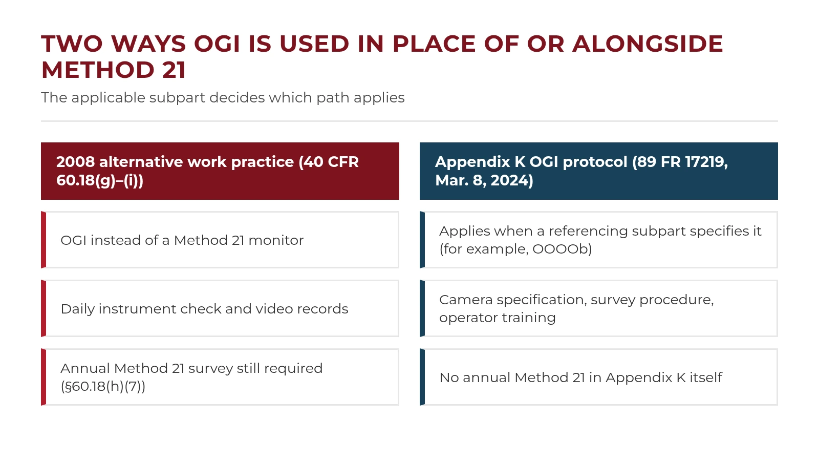
Two-column diagram comparing the 2008 OGI alternative work practice, which still requires annual Method 21, with the Appendix K OGI protocol used by referencing subparts

What Method 21 Can’t Tell You

Method 21 answers one question well: does this component, surveyed this way, read above the leak definition? It is not designed to answer several others, and a monitoring program should plan for those gaps rather than expect the method to fill them.

  • How much a leak emits. The method states that it locates and classifies leaks and is not a direct measure of mass emission rate (Section 2.1). The Appendix K OGI protocol carries the same limitation (Appendix K, Section 1.3).
  • Anything about components it cannot reach. A Type I survey depends on placing the probe at the leak interface. The method itself acknowledges limits: most pressure relief devices cannot be sampled at the sealing seat, and where a pump housing prevents a full traverse, only accessible portions are sampled (Sections 8.3.1.3 and 8.3.1.4).
  • A detector-independent concentration. A reading is tied to the instrument’s calibration and its response to the compounds present, which is why the method sets response factor limits (see detector types).
  • Area-wide coverage. Method 21 screens one component at a time. EPA’s 1992 survey of portable analyzers noted that even a small chemical plant can have thousands of components eligible for Method 21 screening, so survey labour scales with the component count.

Where those gaps matter, rules and programs use other tools alongside or instead of Method 21, including the OGI paths covered above. MFE’s overview of gas leak detection methods compares the wider range of technologies.

Method 21 and OGI Equipment from MFE

MFE does not currently list an analyzer designated for Method 21 in its equipment directories: there is no flame ionization (FID) analyzer, no toxic vapour analyzer, and no product page that names Method 21. The products below are the closest live options for the workflows in this guide, grouped by how they relate to Method 21.

A portable VOC photoionization detector is the closest instrument type, but it is not designated for Method 21; see the note on its card. The optical gas imaging cameras are not Method 21 instruments; they fit programs that use OGI under the 2008 alternative work practice or Appendix K. Product descriptions below are taken from each product’s MFE page.

Portable VOC photoionization detector

Before considering a PID for Method 21 work, confirm it against the method’s Section 6 specifications and Section 8.1 performance checks, and confirm that the compounds you monitor are ones a PID detects. The MFE product page below does not state Method 21 compliance, the instrument’s response time, or its probe dimensions.

1. RAE Systems MiniRAE 3000 PID

RAE Systems MiniRAE 3000 handheld photoionization detector

Offer: Buy or Rent

The RAE Systems MiniRAE 3000 PID is a portable photoionization detector for volatile organic compounds (VOCs), described on its MFE product page as providing rapid and accurate VOC detection for air quality monitoring across various applications, including industrial hygiene, hazardous materials response, and environmental monitoring.

  • Detection range listed as 0.1 to 15,000 ppm, adjustable in 0.1 ppm increments
  • Ships with a 10.6 eV lamp; 9.8 eV or 11.7 eV lamps optional
  • Includes over 200 chemical correction factors
  • Optional calibration kit with 100 ppm isobutylene calibration gas

Method 21 note: The MiniRAE 3000 is not designated for Method 21 on its MFE product page. As a PID, it does not detect methane.

Learn more

Optical gas imaging cameras

These cameras visualize gas leaks rather than measuring concentration at a component interface, so they do not perform a Method 21 survey. Whether a camera can be used for a specific program depends on the path the applicable subpart allows; under Appendix K, the camera specification and operating envelope must be confirmed and documented before surveys. The handheld cameras are listed first, followed by drone payloads. For camera types and selection, see MFE’s guide to OGI cameras.

2. FLIR GF77

FLIR GF77 handheld uncooled optical gas imaging camera

Offer: Buy or Rent

The FLIR GF77 is an infrared camera designed specifically for gas detection, capable of identifying methane and other industrial gases. MFE’s product page describes it as an uncooled infrared camera that is spectrally filtered for methane and other gases.

  • Uncooled infrared camera with real-time gas visualization
  • Uses listed include detection of hydrocarbon gas leaks and monitoring of fugitive emissions
  • Touchscreen LCD, rotating optical block, and eyepiece for viewing in direct sunlight

Learn more

3. FLIR GF320

FLIR GF320 handheld optical gas imaging camera

Offer: For Rent

The FLIR GF320 is a thermal imaging camera used for detecting and visualizing volatile organic compounds (VOCs), with real-time video recording and analysis. MFE’s product page describes it as capable of detecting methane or volatile gases in real time.

  • Gases listed on the product page include methane, ethane, propane, butane, benzene, toluene, and xylene, among others
  • Built-in video recorder, digital camera, laser pointer, and embedded GPS location data for documentation
  • Uses listed include detection of hydrocarbon gas leaks and monitoring of fugitive emissions

Learn more

4. MFE Detect MW (MFE OGI Camera)

MFE Detect MW optical gas imaging camera with handle

Offer: For Rent

The MFE Detect MW (MFE OGI) is an optical gas imaging camera designed to detect hydrocarbon gas leaks. It can be used as a handheld device or a payload, and its product page states that it can be mounted on Boston Dynamics’ Spot robot.

  • 640 × 512, 15 μm pixel-pitch “Hot MWIR” detector with a closed-cycle Stirling cooler
  • Designed to optimize visualization of methane, propane, butane, and many other hydrocarbon gas leaks
  • Built-in RGB camera

Learn more

5. MFE Detect LW

MFE Detect LW long-wave infrared OGI camera payload for DJI drones

Offer: Buy or Rent

The MFE Detect LW is a long-wave infrared (LWIR) optical gas imaging camera payload for DJI M300, M350, and M400 series drones. Its LWIR technology allows the camera to detect methane by capturing the infrared light methane absorbs, visualizing leaks in real time. MFE’s product page states: “The Detect LW complies with OOOOa, b, c, and Appendix K standards, supporting methane emissions detection for regulatory workflows.”

  • Uncooled, high-responsivity focal plane array with 640 × 480 VGA imagery
  • Gas enhancement mode (GEM) for improved gas visualization
  • Available as the standard Detect LW or the Detect LW + RGB, which adds an integrated RGB camera with zoom

Learn more

6. MFE OGI 640

MFE OGI 640 optical gas imaging drone payload

Offer: For Sale

The MFE OGI 640 is an optical gas imaging payload that detects and visualizes gas leaks, built to integrate with unmanned aerial platforms for aerial gas leak detection. Its product page describes pairing it with a DJI Matrice 300 Series RTK drone.

  • 640 × 512 HOT MWIR detector, 15 μm pitch, 3.2–3.42 μm wavelength
  • 25 mm f/1.5 lens; 2x, 4x, and 8x digital zoom
  • Approximately 542 g (1.2 lb)

Learn more

EPA Method 21 FAQ

What response time does Method 21 require?

The instrument response time must be 30 seconds or less (Method 21, Section 8.1.3.2). Response time is measured as the time to reach 90 percent of the final stable reading after a step change from zero gas to calibration gas, with the pump, any dilution probe, the sample probe, and the probe filter in place. During a Type I survey, the probe stays at the maximum-reading location for about twice the response time. See instrument requirements.

How often does a Method 21 survey have to be done?

Method 21 does not set a monitoring frequency. The applicable subpart sets it, along with the leak definition and repair deadlines, and frequencies differ from rule to rule. See how Method 21 fits an LDAR program.

Is there a Method 21 certification?

Method 21 does not establish an operator certification or training requirement, and it does not create an instrument approval program. It sets specifications and performance checks that the instrument must meet, and a survey procedure the technician must follow. Training courses on Method 21 are available, but completing one is not a requirement of the method itself; check your applicable subpart and permit for any training requirements. By contrast, the Appendix K OGI protocol does set operator training, testing, and audit requirements for OGI surveys.

Can a drone perform a Method 21 survey?

Method 21 is written as a close-range survey: the probe inlet is placed at the surface of each component interface where leakage could occur (Section 8.3.1), using an instrument that meets Section 6, including a sample probe no more than 6.4 mm (1/4 in.) in outside diameter. The method does not describe aerial deployment. Drones are used for other leak detection methods, such as aerial optical gas imaging, where the applicable rule allows them; MFE’s guide to drone gas detection covers those options.

What is the difference between Method 21 and Method 22?

Both are EPA test methods in 40 CFR Part 60, Appendix A-7, but they measure different things. Method 21 uses a portable instrument to locate and classify VOC leaks at individual equipment components. Method 22, “Visual Determination of Fugitive Emissions From Material Sources and Smoke Emissions From Flares,” relies on an observer without instruments to determine whether, and for how long, visible emissions occur; it does not determine opacity. For example, 40 CFR 60.18 uses Method 22 to check flares for visible emissions.

Where can I find the official Method 21 text?

The current text is in 40 CFR Part 60, Appendix A-7 on eCFR. EPA’s Method 21 page also links a PDF dated August 3, 2017, which notes that it is not the official version.

Sources

Regulatory text was checked against eCFR and EPA sources in November 2026. eCFR is updated continuously; the annually published CFR is the official legal edition.